Flux Vector Control
Flux vector control is another method of speed control and this feature is also available on some standard inverters which normally operate under V/F control.
There are two methods of flux vector control:-
- Open Loop (sensor less vector).
- Closed loop (with encoder feedback).
Flux vector control principles:-
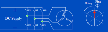
The torque producing and magnetising current vectors are independently controlled. Therefore providing accurate speed / torque control. This is enabled by motor equivalent circuit data of the motor. Motor parameters are entered in the drive followed by an auto tune function. VSD then uses the auto tune data to produce a software model of the motor, for a closely matched speed / torque control.
Vector control in comparison with V/f provides:-
- Improved speed control.
- Dynamic torque response. (Response to rapid changes of input).
- Higher starting torque.
- Accurate speed control.
Closed loop control Can provide full torque at zero speed With encoder feed back.
Sensor less vector control can provide accurate torque control down to 3 - 4 HZ
Typical speed accuracy:-
0.3% is achievable with open loop (Sensor less vector).
0.03% with closed loop (Encoder).
The closed loop vector option has additional cost elements i.e. encoder and its installation. Sensor less vector can be used for most applications, however when speed and dynamic torque control at very low speeds are required then must consider the application closely prior to selection of the of the system
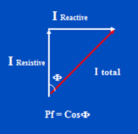
Motor Current (I) is made up of two Current Components
(I) Reactive or Inductive Induces magnetic field in stator and rotor. This is the flux producing current (magnetising Current).
(I) resistive is the torque producing current.
VSD can vary the I Reactive, hence total current and power factor angle.