VSD Control Theory
Why VSD?
Used for simple process control.
In most process there may be a need for controlling a variable of the process. This variable may need to be kept constant or be changed according to a pre-set pattern. variables such as:-
Speed, Pressure, temperature ,flow, etc. Reduce fan noise. Enable operation above motor base speed.
Energy control a saving:-
Reduction of running costs by reducing the power wasted, tuning the motor speed to the load demand. Motors running at full speed but half load waste energy and increase running costs.
Replacing mechanical controls such as dampers, valves & throttling. Reducing maintenance costs by replacing mechanical controls. Improving motor and machine life expectancy by reducing shock loads and mechanical stress.
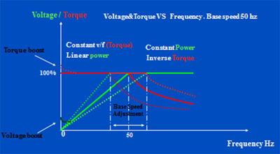
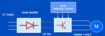
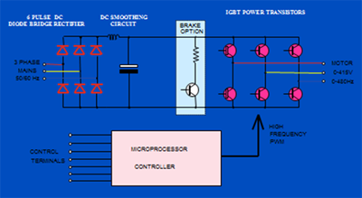
An Electronic VSD converts the fixed frequency, input supply to an output with Variable frequency & voltage which provide speed and hence Torque control.
This is done in Two stages:-
- Rectifying the AC supply to DC
- Chopping the DC supply to an output that resembles an AC supply.
Inverter Operation
The speed of an AC motor is proportional to the frequency of the applied voltage, therefore to vary the speed the frequency must be controlled.
This is achieved by using two power stages within the inverter unit:–
- The first rectifies the fixed frequency AC supply into a DC voltage.
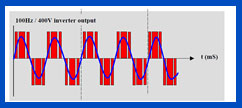
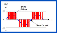
- The second, chopping the DC voltage with transistor switches such as IGBT to supply the motor with a chopped DC waveform.
Inverter Unit
- Integrated Gate Bipolar Transistor (IGBT) is the most common device used in Inverters.
- It can switch at very high frequencies (typically of up to 16 Khz) and still provide a current which is proportional to the voltage.
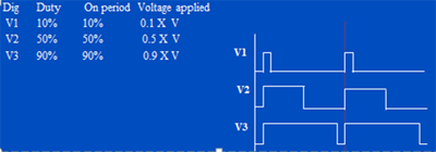
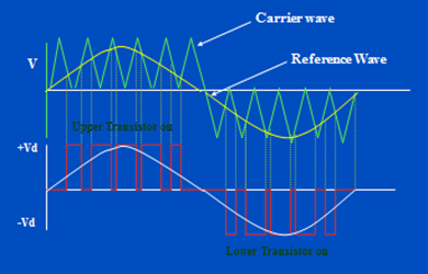
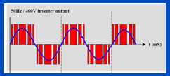
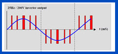
- The high frequency switching technique that is used for converting the DC voltage to a simulated AC, is known as PWM (Pulse Width Modulation).
- Faster the switching frequency, closer is the output to a real AC Sine wave.
- PWM at higher frequencies has the benefit of reducing the heat losses in the motor.
However there are some disadvantages
There may be undesired frequency emissions from the motor and its cables which has to be suppressed. The cable length has also has an effect on the level of interference.
The heat dissipated by the inverter will be increased, although for the specified switching frequency range of the inverter this issue has been taken into consideration in the design, it is still important that for the Correct selection of switching frequency the Inverter manual is consulted.
Inverter Operation